




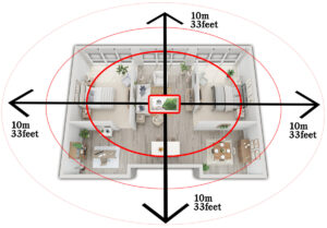


The working radius of this model is 10m/33feet from the installation point and is mostly used for family houses.
The working radius of this model is 10 meters (33 feet) from the installation point under “ideal conditions.” By “ideal conditions,” we mean that the first wall is located 10 meters away. As the signal weakens when passing through multiple walls, the effective distance decreases. Therefore, the best installation position for the device is in the center of the facility.
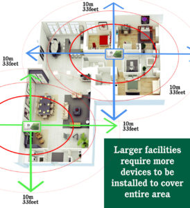
Larger facilities will require multiple devices. If the building has internal reinforced concrete walls with metal mesh, the device’s range will be affected, and additional devices will be needed to address the reinforced walls.
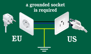
A socket with a grounded connection is essential to achieve optimal results. The grounding wire must be in contact with the soil using grounding probes (rods) or strips.
The walls of your home will be dry within 6 to 12 months, as the device causes the damp to move back to the soil through the microcapillary pores of the walls, similar to how it initially rose.
The unpleasant smell of moisture will disappear much sooner.
| EU | US | |
|---|---|---|
| Brand | GUARDIAN damp removal | |
| Working radius | 10m | 33feet |
| Voltage | 230V | 120V |
| Frequency | ~50Hz | ~50Hz / ~60Hz |
| Current | 10mA | |
| Power | 0,82W | |
| Mechanical protection | IP65 | |
| Protective insulation | IEC class II | |
| Ambient temperature | -25°C do 55°C with temperature stabilizers built-in | |
| Color | Lightgray housing with printed front | |
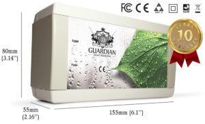
| Product Dimensions | 55mmD x 155mmW x 80mmH | 2.16"D x 6.1"W x 3.14"H |
| Package Dimensions | 10mmD x 17.5mmW x 9.5mmH | 3.9'' x 6.8'' x 3.7'' |
| Recommended Uses For Product | Family houses | |
| Package Weight | 511g | 1.15 Pounds |
| Material | Acrylonitrile Butadiene Styrene (ABS) | |
| Country of Origin | Croatia, EU | |
| Marks | CE, FCC, AAA, ROHS | |
| Applied standards | Device is in conformity with the essential requirements of Electromagnetic compatibility Directive (2014/30/EU), Low Voltage Directive (2014/35/EU), ROHS Directive (2011/65/EU) and FCC rules and regulations(47 CFR Sections 2.906) by applying the following standards: EN IEC 61000-6-4:2019, EN IEC 61000-6-2:2019, EN IEC 61000-3-2:2019, EN 61000-3-3:2013+A1:2019, EN 62368-1:2014+A11:2017, EN 62311:2008, FCC part 15 – radio frequency devices, Subpart B. | |
| Warranty | 10 year | |
The working radius of each model is based on “ideal conditions,” meaning the first wall is at that distance from the installation site. As the signal weakens when passing through multiple walls, the effective range decreases. Therefore, the best position for installation is in the center of the facility. Larger facilities require multiple devices. If the house is constructed with internal reinforced concrete walls containing metal mesh, the device’s effectiveness will be reduced. In such cases, multiple devices are needed to bridge the reinforced walls.


If you purchase this device, you must have a 120V/50-60Hz or 230V/50Hz power supply available, and a functioning SOCKET WITH A GROUNDED CONNECTION intended solely for this device.
QUALITY GROUNDING IS MANDATORY TO ACHIEVE GOOD RESULTS (the grounding wire must be in contact with the soil using grounding probes (rods) or strips). If extension power cords are used, they MUST also contain a grounding wire.
The device is a double-insulated electrical appliance that uses reinforced protective insulation in addition to basic insulation (IEC class II), and grounding for enhanced user protection against electric shock.
The device does not require batteries.
The device can be placed on the floor, a wooden or plastic table, or a shelf (any material except metal), or it can be attached to the wall using the two provided dowels and screws from the box. If you choose the second option, follow these instructions:
Position the device near the socket within the range of the device’s connection cable. Fold the installation manual as shown in the picture and use it as a marking template. Mark the drilling points on the wall, spaced 113 mm (4.44 inches) apart, according to the template.

On the marked spots, drill holes with a Ø5 mm (13/64″) drill bit, insert the dowels, and then screw in the provided screws so that approximately 10 mm (0.4 inches) remain protruding from the wall.

Place the device onto the screws, aligning the wider part of the back holes with the screws. Gently push the device down so that it hangs securely in the narrower part of the holes.

Insert the connection cable into the power slot on the bottom of the device, and plug the other end into a functional, grounded socket.

